wirebond_title.gif

How Downbonds are Handled

Many packages support downbonds - wirebonds to the die paddle or to a ring.

To use downbonds with Wirebond the designer must first define a downbond area on the package drawing by using a zero width closed polyline on its own layer. See the illustration below for different ways of drawing rings or paddles.
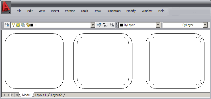
there are several different ways of drawing rings or paddles

Once such a layer is defined, Wirebond can be instructed to attach certain die pads, specified by net or even by die pad number to the paddle. These wires are attached after the IO wires are placed in order to place them in between the IO wires.


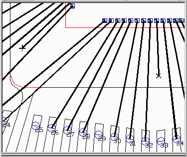
The downbonds are placed between the IO bonds. You can also see the X marker used to identify downbonds.

The distance from the edge of the ring is set in the Pads & Rings tab as the Ring Spacing parameter. A negative value of ring spacing offsets inward from the edge of the ring and a positive value offsets outward.

  downbond9.gif

Drawing Rules

  1. Rings or Paddles must be drawn using a zero-width closed polyline.

  2. Rings or paddles that represent different nets (i.e. a VSS ring and a VDD ring) must be drawn on separate layers.

Wirebonding Rules

  1. The program will attempt to place downbond wires between the wires assigned to fingers as the angle for a downbond has some flexibilty.

  2. The program will not place a downbond if it requires that the bond wire cross from one side of the die/package to the other.

  3. The "exclusive rule" does not apply to downbonds attached to ring or paddle layers.


 Page Topic
  1  Overview of Wirebond
  2  Importing GDSII
  3  Die Pad Recognition and Numbering
  4  Placing the Die
  5  Smart Wire
  6  How Downbonds are Handled
 
 Page Topic
  7  Wire Connection List
  8  Wire DRC
  9  Sorting Wires by Tiers
  10  Auto Documentation
  11  Title Border Template
  12  Filling Out the Title Border