 |
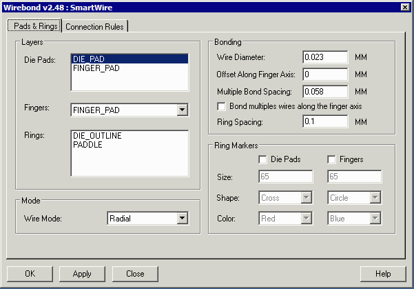
Smart Wire - Automatic WiringOnce the die has been placed into the package it must be wirebonded. There are two separate approaches to wirebonding - a rule based approach and a connection list approach. Depending on the nature of your data, one or the other will be preferred. Rule Based - the user defines a series of rules such as: All Die Pads with Net GND go to Ring GND. To follow this rule the program examines the net property of each die pad, and if the net property is equal to GND then it attempts to wirebond to a ring with name GND. Connection List - in many cases the user knows exactly which die pad goes to which package finger. A table is created with the die pad in column 1 and the finger number in column 2 and the program reads this to drive the wirebonding. Wirebonding Setup Prior to defining the rules and running them, the user must first set up the basic wirebonding parameters. This is done from the setup tab.  In this dialog you define which layers your die pads lie on, which layer your fingers lie on and which layers represent ring or paddles for downbonding. You also define the wire diameter and how far apart wires will be spaced when multiple wires are placed on a single finger. Once all the basics are set, you move over to the Connection Rules tab |
|
Rule Based Wiring
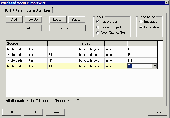
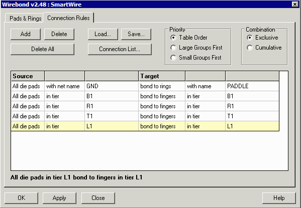
A series of "rules" can be defined that drive the wirebonding. The program attempts to follow these rules. Rules can be based on: tier to tier bonding, net to net bonding, pin number to pin bonding, net to ring bonding. For example, the simplest rule would be merely to bond all die pads on the left side of the die to fingers on the left side of the package (repeat for top, bottom and right side)  Assuming your die pads have nets associated with them, you might want all die pads with net name VSS downbonded to the "paddle" (a layer on the package we created). In this case you might apply the following rule prior to the tier based rules. You would make sure this rule was "first" so that these were not bonded to fingers using the other rule.  |
|
Connection List Wiring For many leadframe applications the package designer has put together a table that maps each die pad to the desired package pin (or to the paddle). We call this a connection list. Details on on this page .... |
|
|