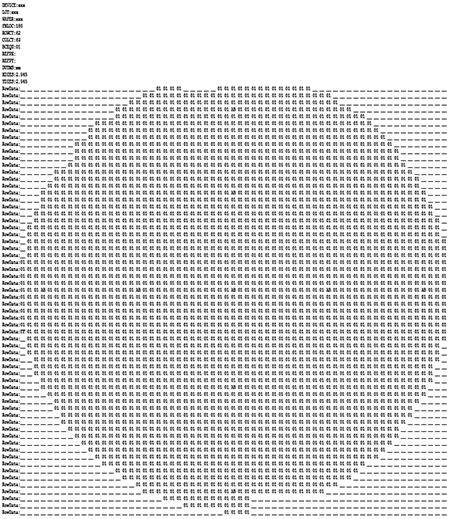

Wafer maps are used in the back end of the IC manufacturing process to annotate the die on a wafer - the annotation may indicate whether the die is good or bad, the "grade" of the device or whether this device is a reference device.
Version 2.0 is a complete rewrite of our original product. Why? When we initially created the first version of wafer map we did not appreciate how many wafer formats were in use. So we did not structure it in a way to easily add more input and output formats. Adding a format was time consuming and in-efficient.
After several years of struggling with the architecture of V1, we decided to re-start from scratch. V2 is designed from the ground up to add additional input and output formats.

SINF formatted wafer map
The formats that Wafermap Convert v2 currently reads are:
WaferMap Convert v2 currently writes:
Formats not currently supported but under development:
Additional input and output formats will be added as clients request them.
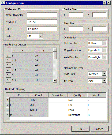
Often when converting from one format to another, the user finds that data required by the output format is not present in the input format. Wafermap Convert will display a window that enables the user to manually fill in the missing data.
This is especially important because many simple input formats do not clearly define where the 0,0 position is located; many do not include the data units and some do not include the flat orientation.
Various Map formats use different terms for parameters and measurements. Out glossary of terms provides some details on terms used and can help when converting from one format to another.

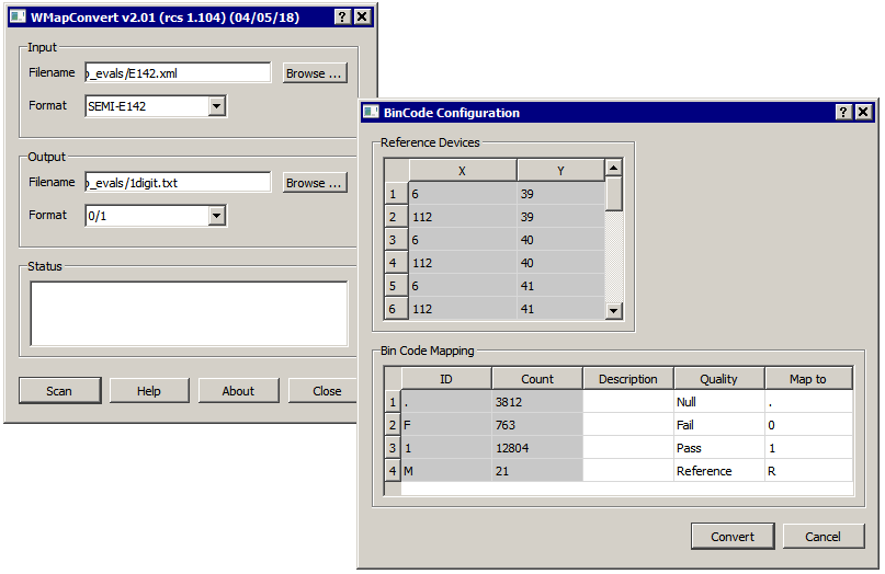
From the main dialog select the file and identify its format.
Then select the desired output format and provide a file name to produce.
Press SCAN; the program will scan the input file and present a screen showing what information it was able to extract.
For more details, go to the Wafer Map Convert user manual.

WMapConverter V2 main dialog and configure dialog. Items in "gray" cannot be edited.