Hextract Web Page Header


The Unit Cell Design

The Wafer/Die Settings

Matching Existing Die

Generating the Array
with GDS-SR

Plating on RDL/UBM

Clip to a Round Boundary

Knocking Out Openings

Dropping in the FIDS

Solder Stencil Issues


GDS-SR A Stepping program for Round Wafers

Some years ago we developed GDS-SR a specialized stepping program for round wafers. The initial user was working on MEMs circuits and his designs were small in complexity compared to an IC chip. The GDS-SR turns out to be very useful for Wafer scale masks.


    To use the stepping part of the program the user specifies:

    wafer diameter, margin and flat(s)

    stepping values in X and Y and any offset if needed


The program steps the die out to the edge of the wafer's margin but does not place any die that is not completely inside of the margin.


To use GDS-SR to step our redistribution circuit, we first enter the wafer size and margin. Notice that in this case we have actually entered a diameter that is larger than our wafer.

This is to overcome GDS-SR's behavior of not inserting a cell if any part of it crosses the edge of the boundary. Since we are going to use another program to smoothly clip the data, we need the data to extend out past the desired clipping boundary.
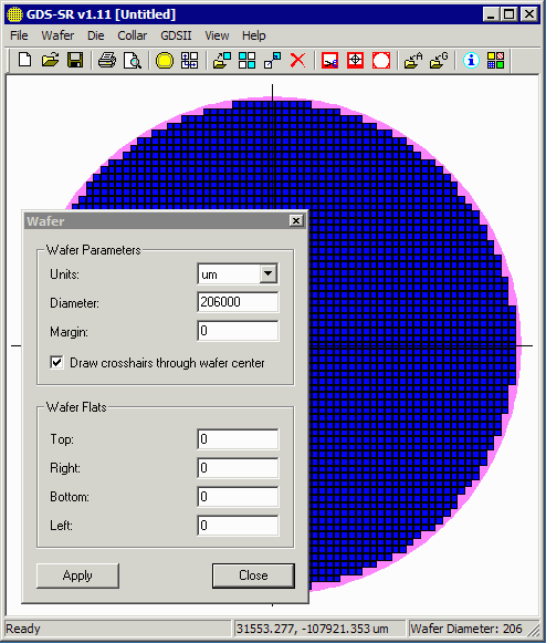
  GDS_SR dialog


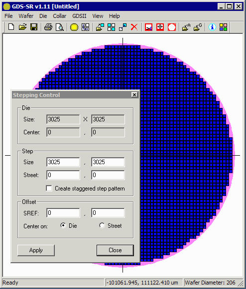
After loading our unit cell we then set the stepping parameters. Because we drew 1/2 of the street as part of the cell, we will step to exactly the extents of the cell.

If we needed to offset our array to match the die already on the wafer we would enter the offset distance into the field marked SREF Offset.

  GDS_SR stepping parameters


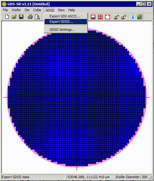
To produce an array of the unit cell all we have to do is to select: Export GDSII and save the new file.

We'll call it array_all.gds.

If you'd like to examine the array just click on the link below:

array_all.gds   298Kb GDSII stream
  GDS_SR stepping parameters


NEXT Why We Need a Smooth Round Clip ...


  Download   Application Note   Revision History   Price