HEXtract Command Line Syntax
We'll create a simple batch file that calls HEXtract 5 times -- once for each layer. However because there are so many cutouts, we will use an include file to list the cutouts.
Here is the contents of the include file, cutouts.txt
  # MASK CUTOUTS
  # LLX        LLY          URX         URY
  # WAFER_ID
  3100.000,    92520.000,   16750.000,  95650.000
  # FID1
  -10320.000,   93410.000,   -8150.000,  95020.000
  # FID2
 8150.000,    -95020.000,    10320.000, -93410.000
  # ALIGN1
  -82695.390,  50150.000,  -81195.390,  51650.000
  # ALIGN2
  -82695.390, -51650.000,  -81195.390, -50150.000
  # ALIGN3
  81195.390,   50150.000,    82695.390, 51650.000
Here is an annotated command line for one mask
   c:\wcad\hextract\hxtractor32.exe      <- launches the hextract program

      via1_after_clip.gds                <- the input file

        via1_bf_targets.gds               <- the output file

          -layers:1                      <- only process layer 1 (ourVIA1)

            -complement                  <- forces the cutout option

               -windows@cutouts.txt      <- gets cutout list from file ...
We'll repeat the same command line changing the file names and layers each time. The only difference will be on the solder mask layer. For that layer we will use the additional option -drop_partial_poly.
hxtractor32.exe   via1_after_clip.gds   via1_bf_targets.gds   -layers:1
-complement -windows@cutouts.txt

hxtractor32.exe   rdl_after_clip.gds    rdl_bf_targets.gds    -layers:2
-complement -windows@cutouts.txt

hxtractor32.exe   via2_after_clip.gds   via2_bf_targets.gds    -layers:3
-complement -windows@cutouts.txt

hxtractor32.exe   ubm_after_clip.gds    ubm_bf_targets.gds     -layers:4
-complement -windows@cutouts.txt

hxtractor32.exe   solder_after_clip.gds solder_bf_targets.gds  -layers:5
-complement -windows@cutouts.txt -drop_partial_poly
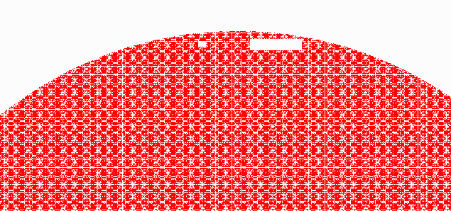
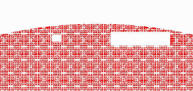
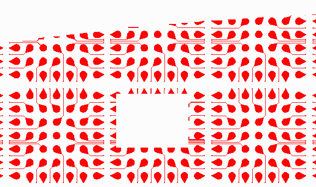
Here is what the RDL layer looks like after knockouts generated by HExtract:

top section of wafer ...

zoomed in ...

zoomed in again ...
If you'd like to examine the GDSII files after the
target and fid windows have been knocked out,
click on the file below:
