HEXtract Command Line Syntax
We'll create a simple batch file that calls HEXtract 5 times -- once for each layer. You can see it below along with some annotation. (the real command line has no breaks but we've introduced them merely for readability.) We are assuming all input and output files are in our "current" directory.
   c:\wcad\hextract\hxtractor32.exe      <- launches the hextract program

      array_all.gds                      <- the multi-layer arrayed data

        rdl_after_clip.gds               <- the output file

          -layers:2                      <- only process layer 2 (our RDL)

            -roundwindow:0,0,97500,12,2  <- round window centered at 0,0 w radius = 97500
                                         <- the last two parameters control the smoothness
We'll repeat the same command line changing the layer each time and the output file name. The only difference will be on the solder mask layer. For that layer we will use the additional option -drop_partial_poly.
hextractor32.exe array_all.gds via1_after_clip.gds   -layers:1 -roundwindow:0,0,97500,12,2
hextractor32.exe array_all.gds rdl_after_clip.gds    -layers:2 -roundwindow:0,0,97500,12,2
hextractor32.exe array_all.gds via2_after_clip.gds   -layers:3 -roundwindow:0,0,97500,12,2
hextractor32.exe array_all.gds ubm_after_clip.gds    -layers:4 -roundwindow:0,0,97500,12,2
hextractor32.exe array_all.gds solder_after_clip.gds -layers:5 -roundwindow:0,0,97500,12,2
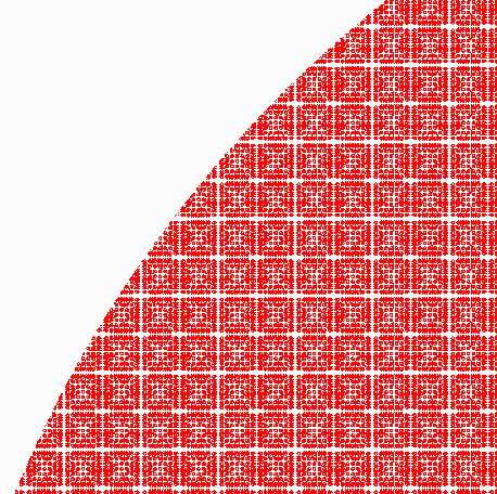
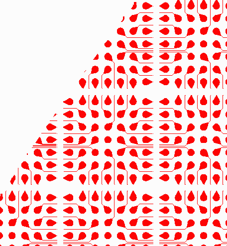
Here is what the RDL layer looks like after a round clip by HEXtract.

full view of wafer ...

zoomed in ...

zoomed in again ...
