Netex-G web page header
NETEX-G Links

Overview
• Introduction
• Applications
• User Interface
 
Inputs
• Gerber File Requirements
• Vias from Drill Data
• Layer Stackup
• Wire Bond Data
 
Assigning Nets and Nodes
• From ASCII Table
• From AIF
• From IPC356
• From GBRVU

Outputs
• ASCII Output
• Ansoft ANF
• Geometry Options
• GDSII
• DXF
 
Proximity Effect
• What is a Proximity Net?
• What is a Neighbor Net?
 
 
Extractions
• Extracting Nets
 
 
Netex Engine
• Program Flow
• Job File Syntax
• Command Line Syntax
• drl2gbr engine
• generating wire coords

NETEX-G User Interface

A series of menus and dialog boxes are used to collect the required information needed to run NETEX-G as well as configuring the conversion parameters. The screen shots and comments shown below describe how to use these dialogs.

The screen shot below has "hotspots" over the different menu buttons and fields. Place your cursor over a hot spot and click to get details.
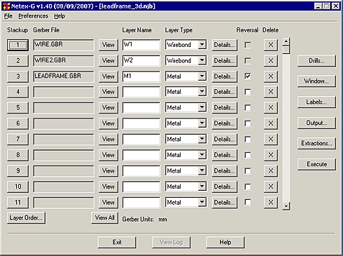

NETEX-G Main Menu press to select the Gerber file for this layer the Gerber file for this layer View this Gerber Files View all the Gerber Files this is the units of the Gerber files assign an arbitrary name to this layer metal, dielectric, soldermask or wirebond thickness, material and electrical properties check if this layer is reverse polarity check if this layer is reverse polarity Enter drill files and layers they connect Select Window attach net and node labels Define type of output define extraction by net or node Execute Program set the desired conversion preferences file drop down menu.